

By the end of this guide you’ll have diagnosed, repaired or replaced a wall-mounted garage opener control button, tested wiring and safety features, and optionally planned an upgrade to a modern control panel. Typical time: 45–120 minutes depending on complexity. Skill level: basic DIY (comfort with hand tools and low-voltage wiring).
Before you start
- Ensure you have basic DIY experience: screwdriver use, handling low-voltage wires, and following step sequences.
- Turn off power to the garage opener at the wall switch or unplug the unit; do not rely on the wall switch alone.
- Gather tools listed below and a multimeter rated for low-voltage (<24V) continuity/voltage checks.
- If you have an active opener warranty, check whether DIY work affects coverage.
Core tools & materials (also repeated in the Tools and Safety section): insulated screwdriver set, 18–22 AWG wire stripper, needle-nose pliers, 2–4 inches of 18–22 AWG stranded low-voltage wire (if replacing), electrical tape, multimeter or voltage tester, replacement wall button or control panel.
Understanding Garage Door Opener Buttons and Controls
This section explains what the garage door opener button and its wall control panel actually do, and how they fit into the opener system. A wall control is a low-voltage switch or button mounted near the interior entry to your garage. Pressing the button sends a simple signal—usually a short low-voltage circuit closure—to the opener motor to toggle open/close, stop, or trigger features like lighting or vacation lock.
Most wall-mounted controls communicate via two low-voltage conductors to the opener’s terminal strip; some modern panels add data lines or wireless modules for smart features. The control panel can be as simple as a single garage door button or a multi-button module that includes a keypad, light control, and lock. Because this guide focuses strictly on the wall button and panel, it does not cover full opener motor installation or gear replacement.
For a deeper view of how the opener interacts with mechanical parts and lift systems, review resources on broader system design and lift options before upgrading controls.
garage door lift system options
To visualize the opener components that connect to wall buttons, consult a parts diagram guide if you need a refresher on terminals, sensors, and drive components.
garage door opener components guide
Types of Garage Door Opener Buttons and Switches
Different button types change installation, wiring, and behavior. Below are the common varieties and the pros and cons of each.
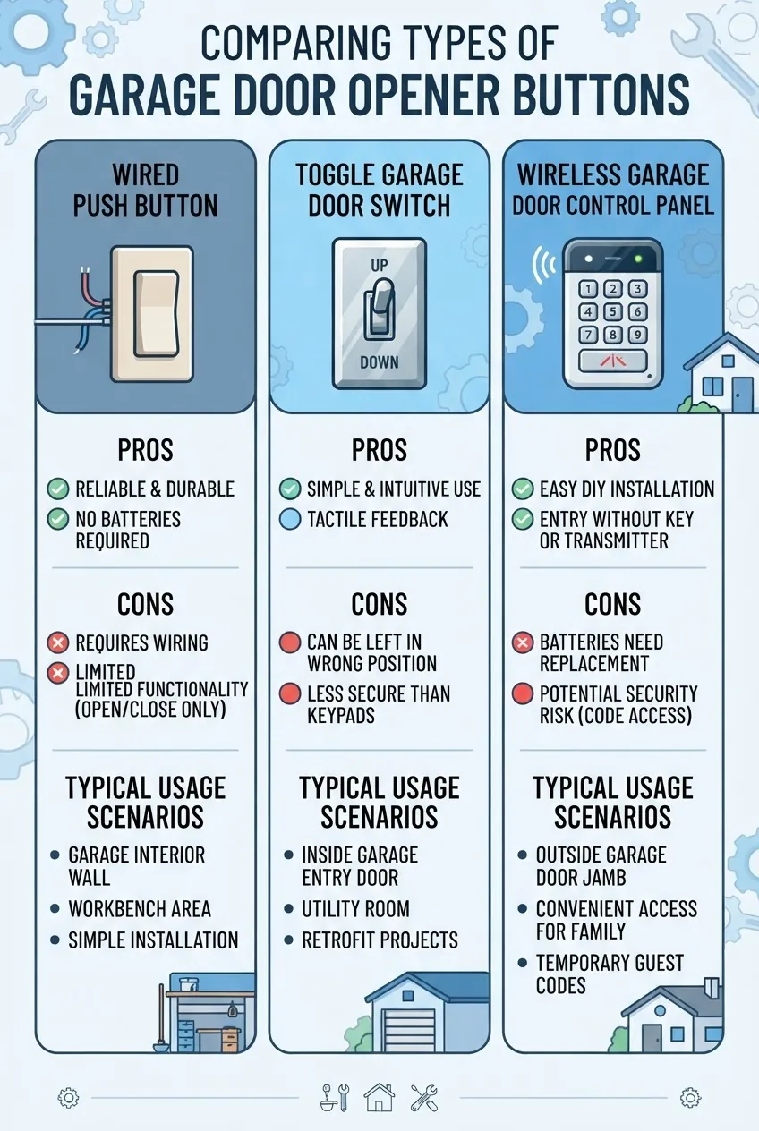
- Wired push button (momentary contact) — a simple push-button that closes the circuit only while pressed. Pros: reliable, low-cost, low-voltage. Cons: limited features; physically exposed to wear.
- Wired toggle or rocker switch — toggles between open and close or uses momentary action depending on model. Pros: robust tactile feel, familiar operation. Cons: can confuse if not wired for momentary operation; heavier wear if used as toggle.
- Multi-function control panel — includes push button plus lights, lockout, or keypad. Pros: feature-rich, convenient. Cons: more wiring, potential for greater failure modes.
- Wireless wall switch / battery keypad — communicates via RF to the opener or to a hub. Pros: easy retrofit, no wiring required. Cons: battery maintenance, possible RF interference, slightly higher latency.
- Capacitive touch panel — modern panels with touch sensors and LED indicators. Pros: sleek, fewer moving parts. Cons: requires power/firmware and may need specialized wiring.
Quick comparison table
| Type | Typical wiring | Best for |
|---|---|---|
| Wired push button | 2 low-voltage wires (momentary) | Basic open/close control |
| Toggle/rocker switch | 2 wires; sometimes latching | Durable mechanical use |
| Wireless keypad | Battery powered RF module | Retrofits without new wiring |
If you want to match button types to opener types, review guides on opener selection to ensure compatibility between switch behavior and drive logic.
How to Diagnose Issues with Garage Door Opener Buttons
Diagnosis is systematic: start at the button, then check wiring, then the opener terminals and logic. Follow the checklist below to isolate a button or control panel fault from a broader opener problem.
- Confirm basic behavior: Press the wall button and listen—does the opener motor click, hum, or do nothing? A click at the opener indicates the signal arrived; silence suggests wiring or button failure.
- Check the safety sensors: Many openers disable button commands if photoelectric sensors are blocked or misaligned. Inspect sensor LEDs and alignment.
- Test continuity at the button: With power off to the opener, remove the wall button cover and use a multimeter continuity mode across the two conductors. A momentary contact should show continuity only while pressing.
- Verify voltage: With the opener powered and button pressed (careful—follow safety steps below), measure across the opener’s terminal strip; you should see a low-voltage closure typically near 0V when closed, open-circuit when not pressed. Exact voltages vary by manufacturer but are usually under 24V DC/AC.
- Swap terminals: If you have a spare compatible switch, temporarily wire it to the opener to isolate whether the issue is the button or the opener’s input circuit.
- Inspect wiring: Look for broken conductors, corroded terminal screws, or signs of rodent damage. Low-voltage wiring often uses 18–22 AWG; verify gauge and secure connections.
- Check for firmware or lockouts: Some modern panels include a “lock” or “vacation mode” that disables wall buttons—try the manual reset per your opener’s user guide.
If these steps point to the button or wiring, proceed to replacement. If the opener doesn’t react even with a confirmed working button, suspect a deeper controller or motor issue.
Tools and Safety Precautions for Button Replacement
When working with wall switches and control panels, treat the wiring as low-voltage but respect nearby mains wiring and moving doors. Follow these numbered safety tips and use the listed tools.
- Power off the opener motor — Unplug the opener or switch off the dedicated outlet; do not rely on just the wall switch to isolate power.
- Use a multimeter — Verify absence of voltage before touching terminals. Use a meter rated for at least 24V DC/AC and continuity checks.
- Wear eye protection and avoid loose clothing — Garage doors are large moving masses; never test with anyone under the door or with fingers near rollers/tracks.
- Observe manufacturer safety guidance — For example, follow the Consumer Product Safety Commission’s guidance on garage door safety and testing for entrapment protection. Consumer Product Safety Commission
- Follow local wiring code for low-voltage runs — While low-voltage often has fewer restrictions, some jurisdictions require specific separations from mains wiring; consult the National Electrical Code or local authority. National Fire Protection Association
- Have a helper for heavy tasks — If you need to remove larger panels or reach high-mounted modules, have a second person steady a ladder.
Tool list (minimum):
- Insulated Phillips and flathead screwdrivers
- 18–22 AWG wire stripper and crimper
- Multimeter (voltage & continuity)
- Needle-nose pliers and small adjustable wrench
- Replacement switch or control panel rated for low-voltage garage door use
For electrical safety recommendations, see the National Safety Council’s electrical tips. National Safety Council
Step-by-Step Guide to Replacing a Garage Door Opener Button
This is the working procedure you can follow on most residential openers with a two-wire wall switch. If your panel includes additional functions (keypad, LCD, battery), treat those as separate modules—follow manufacturer instructions for added complexity.
Estimated time: 45–90 minutes. Difficulty: low for basic push-button swap; moderate if replacing a multi-function control panel or running new wire.
- Turn off power and secure the door
- Unplug the opener from the mains outlet or switch off breaker to the outlet (note the breaker number). Wait 10 seconds for any capacitors to discharge.
- Lower the door fully and clamp it or engage the emergency release to prevent movement during testing.
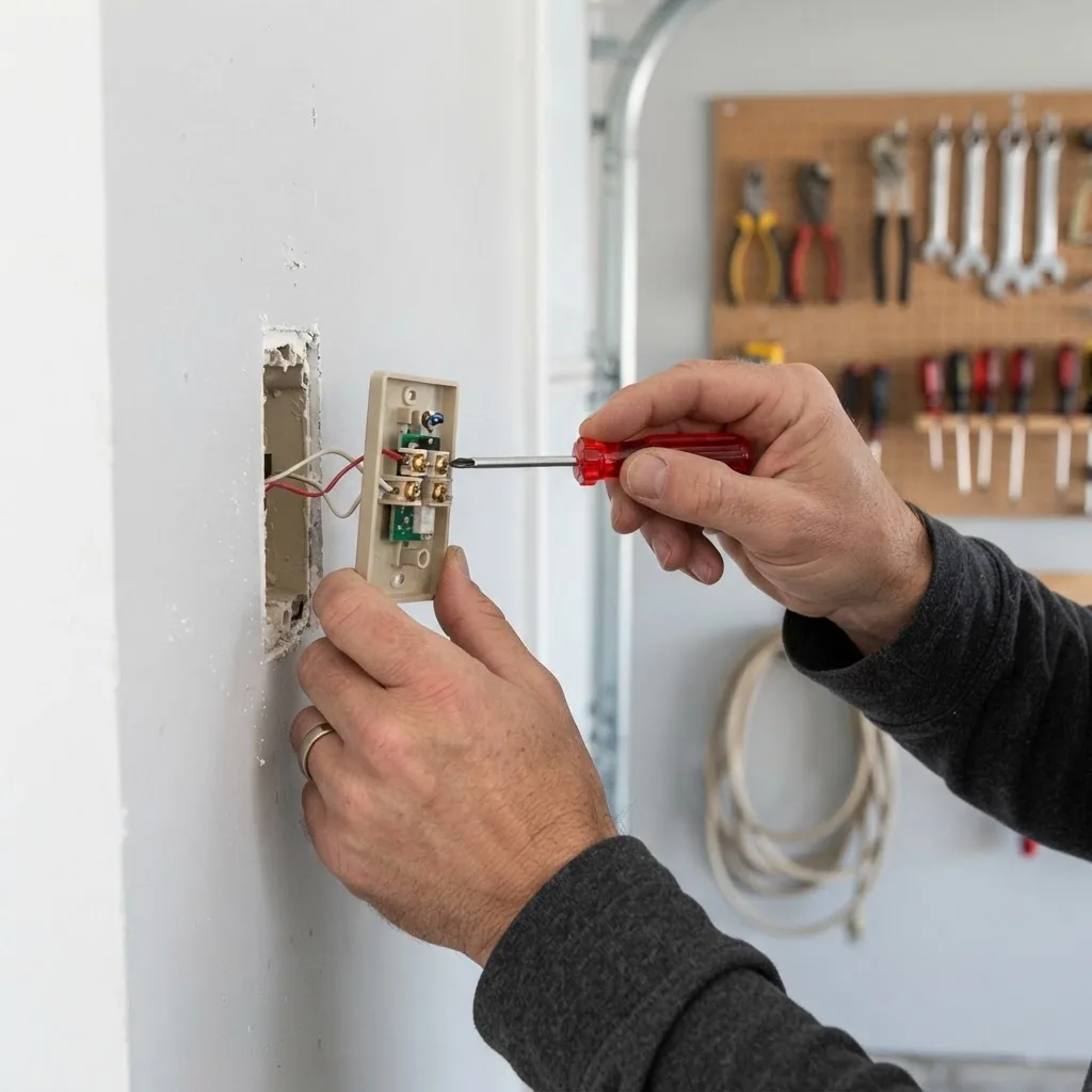
- Remove the old button cover
- Use a screwdriver to remove screws holding the wall plate. Keep screws in a small container.
- Gently pull the plate away to expose the terminal strip and wires. Photograph the wiring for reference (phone photo works).
- Identify and label conductors
- You should see two low-voltage wires attached to the button terminals (commonly labeled “Wall”, “Wall Switch”, or with icons). They are typically 18–22 AWG and colored red/white or black/white depending on run length.
- If there are more than two wires, label each with tape and note which pair connects to the opener’s “Term” screw terminals.
- Test continuity
- Set your multimeter to continuity. With the opener still unplugged, press the button and confirm the meter beeps/closes only while pressing. If not, the button assembly is faulty.
- Disconnect the old switch
- Loosen terminal screws and free wires. If the wires are frayed, cut back 1/2 inch and strip 1/4 inch of insulation from each conductor.
- If wires are under a screw clamp, you can leave a small pigtail if necessary, but ensure solid contact.
- Prepare the new button or panel
- Verify the replacement is rated for garage door low-voltage circuits (no mains wiring on the control side). Modern replacement kits will specify compatibility with momentary contact systems.
- If installing a multi-function panel, note additional wires or battery compartments and read the included wiring diagram.
- Wire the new switch
- Attach the two conductors to the new switch terminals. For momentary push-buttons, polarity doesn’t matter; for some panels polarity may matter—follow manufacturer labeling.
- Use small terminal screws to clamp conductors; torque by hand until snug to avoid damaging small terminals (approx. 0.5–1.0 Nm). If using wire ferrules, crimp them for a cleaner connection.
- Secure any extra wires with cable clamps and tidy wiring behind the plate to avoid pinching when mounting.
- Mount the new plate and secure
- Align the new plate and fasten screws without over-tightening; over-tightening can crack plastic bezels or deform metal plates. Tighten until snug plus an extra 1/8 turn.
- Restore power to the opener (plug in or switch on the outlet). Wait 5–10 seconds for system boot.
- Functional test
- Stand clear of the door. Press the new wall button once to issue a toggle. The door should start moving. If it reverses or doesn’t move, press again to stop and proceed to diagnostics.
- Test additional features (light, lock) if the panel supports them; follow panel labels for short vs. long presses—note the required durations: typically <2 seconds for toggle, >3 seconds for programming/lockout.
- Verify safety reversal and sensors
- Place a 2×4 flat on the floor where the door closes and press the button to close the door. The opener should reverse on contact. If it doesn’t, stop and check opener force and travel settings—do not rely on this test if the opener is not functioning correctly.
- Check photo-eye alignment: ensure LEDs are steady (green/amber depending on model) and mountings are secure.
- Final checks and cleanup
- Confirm terminal screws remain snug after initial use. Inspect for heat or burning smell—stop if present.
- Document the work (take photos), and store spare parts and tools. If you changed wire gauge or routing, note it on a maintenance label behind the wall plate for future reference.
If you found wiring or logic issues during testing, consult full opener installation instructions for setup options.
garage door opener installation and setup
If you decide the whole opener is at end-of-life or misbehaving beyond the button, consider a replacement.
garage door opener replacement guide
Common mistakes and how to avoid them
I once connected a new multi-button panel without verifying the opener’s required momentary vs. latching behavior; the door behaved erratically until I rewired for momentary contact. I always test with a temporary jumper first now. Another time I over-tightened terminal screws and split the plastic housing—use gentle torque and ferrules on stranded wire.
Checklist — verify your work
- Button press triggers opener reliably from wall control (press, door moves).
- Safety sensors reverse the door on obstruction.
- All terminal screws are snug; no exposed frayed wire beyond 1/4 inch.
- Panel mounted square and screws not over-tightened.
- Any programmable lockouts or vacation modes are set per preference and documented.
When to call a professional
If the opener does not respond even with a known-good button, if you detect burned wiring or smoke, if mains wiring is involved near the control, or if door balance and springs seem off (door is heavy to lift), call a licensed technician. Also consider pro help if your work may affect a warranty.
Wiring and Compatibility Considerations
Wiring basics: most residential wall switches use two low-voltage conductors to the opener’s terminal strip. These conductors are typically 18–22 AWG and are treated as low-voltage circuits (not mains). “Low voltage” refers to circuits under 50V, commonly 12–24V, which reduces but does not eliminate risk.
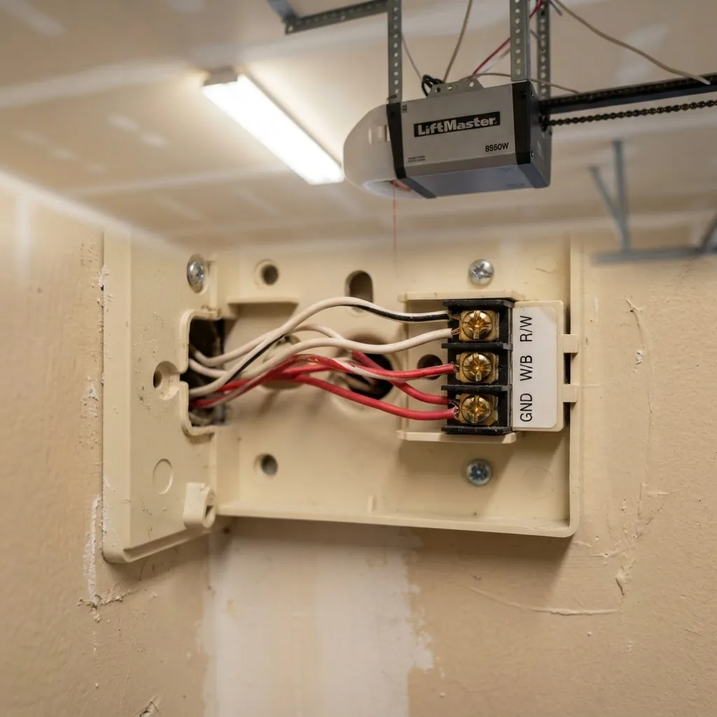
Common terminal labeling you may encounter on openers:
- “WALL”, “PUSH”, or “W”: two terminals for wall switch
- “LIGHT” or “L”: switched output for light circuits (may be mains on some models—read the manual)
- “LOCK” or “VAC”: programming/lock terminals for safety lockouts
Compatibility tips and practical wiring rules:
- Use the same gauge wire for the entire run—mixing 18 AWG with 22 AWG across long runs can create increased resistance.
- Keep low-voltage wiring separate from mains cables by at least 50mm, and avoid running parallel long distances together to reduce induced noise if local code requires separation.
- For runs over 50 feet, use 18 AWG to minimize voltage drop; for under 50 feet, 20–22 AWG is usually fine.
- Label both ends of control wires at the opener terminal and at the wall plate for future service.
- If you find more wires than expected, trace them: some panels use extra conductors for LED indicators or for wired keypads.
If you want cost/installation context when considering an upgrade to a complex control panel or adding new runs, review installation pricing to budget labor and parts.
garage door opener installation and pricing guide
For mechanical and cable systems tied to the opener, see detailed diagrams covering cables and parts for safe coordination between controls and physical systems.
garage door parts and cable systems
Be aware of brand-specific control logic: while terminal function is standardized, programming steps, voltage expectations and lockout behavior vary. If your diagnostics point away from the button toward the opener’s drive or gears, consult repair guides.
garage door opener gear repair tips
Upgrading and Customizing Your Garage Door Control Panel
Upgrades range from swapping a worn push button to installing a smart control panel or wireless keypad. Consider these trade-offs:
Wired replacement — retains reliability and no batteries; best when you already have neat runs and the opener supports extra features.
Wireless keypad or wall switch — fastest retrofit with minimal wiring. Expect to manage battery replacement and occasional pairing issues. Wireless panels typically pair to the opener using RF and require following a programming sequence.
Smart integrations — Wi‑Fi-enabled panels add remote monitoring and smartphone control. They often require a compatible hub or a manufacturer’s smart module; evaluate whether your opener supports retrofit smart kits.
For brand-specific installation steps when switching to a proprietary panel (e.g., certain smart modules or brand accessory kits), consult the manufacturer’s install guide for required wiring or jumpers. For a common popular brand install reference, see installation guidance for widely-used kits.
LiftMaster garage door opener installation
Retrofit checklist when upgrading:
- Confirm opener terminal labels and voltage compatibility.
- Decide on wired vs wireless based on convenience vs reliability.
- Plan wire runs (choose 18 AWG for runs >50 ft).
- Reserve space for batteries if installing a wireless keypad.
- Document programming steps and record default codes.
Troubleshooting Common Garage Door Button Problems After Replacement
Short FAQ-style troubleshooting for post-replacement issues:
Button doesn’t respond
Check power to the opener, verify continuity across the new switch with power off, and confirm correct terminals at the opener. If the opener still doesn’t react, test with a known-good jumper wire directly at the opener terminals to isolate the wall switch.
Intermittent signal
Intermittency usually means a loose terminal, broken wire, or corroded contact. Re-seat and re-strip connections, use ferrules on stranded wire, and replace any brittle or oxidized cable sections.
Stuck or lagging button
Mechanical sticking calls for cleaning or replacing the physical switch. For touch/capacitive panels, reset power and check for moisture at sensors; replace the panel if faults persist.
Fuse or circuit trip (rare)
If a mains fuse blows when the opener is powered, there may be a short in the lighting circuit or an improperly connected mains feed on a multi-function panel—stop and call a qualified electrician.
Need to reprogram or reset
Many panels require a factory reset after replacement; consult your opener guide for the reset sequence. If you have trouble programming remotes or wireless panels, follow the programming steps specific to your opener model.
Common mistakes and how to avoid them
I once wired a new panel and left an old resistor lead in place; the opener behaved intermittently until I removed the legacy resistor. My rule now: cleanly terminate and label only the active pair. I also learned to always test with a jumper across terminals at the opener before assuming a wall switch is good.
Conclusion
Replacing or upgrading a garage opener switch or wall-mounted garage door control panel is a straightforward DIY task when you follow proper safety, identify the correct wiring, and test systematically. If you followed the steps above, you should have a functional button, confirmed safety reversal operation, and documented wiring for future service.
Ready to upgrade further or need parts and pricing? Review the installation cost guide to decide whether a full opener replacement or a smart retrofit makes sense for your garage.
garage door opener installation and pricing guide
Call to action: If you’re unsure at any step, stop and contact a licensed garage door technician—safety and correct operation are worth professional support.