Garage door opener installation — by the end of this guide you’ll have a fully mounted, wired, and programmed automatic opener with safety features tested; expect 4–6 hours for a single DIYer and basic electrical skills (level: confident DIYer with ladder experience).
This hands-on guide assumes familiarity with common hand tools and basic electrical safety; it walks you step-by-step through preparations, mounting, wiring, sensor alignment, automatic programming and post-install checks so you can finish with a safe, reliable system.
Before you start
Confirm the garage door is balanced and rolls smoothly with springs intact.
Obtain permits if required by local codes for electrical work or structural changes.
Have a helper available for heavy lifts and alignment during final mounting.
Turn off power at the breaker when working on wiring; plan next-day testing after installation.
Introduction to Garage Door Opener Installation
This section explains the benefits of an automatic setup, an overview of the process, and why many homeowners choose to install themselves. Installing an automatic opener adds convenience, remote access and safety features like auto-reverse and photo-eye sensors. Proper installation reduces accidents and extends opener longevity.
Choosing the right system starts with understanding garage door opener drive types: chain drive (durable, louder), belt drive (quieter, slightly pricier), and screw drive (fewer moving parts, mid-noise). For background on manual vs. powered mechanisms, see our resource on garage door lift systems.
Why DIY? Many homeowners save 20–40% of installation costs by doing the work themselves, provided they follow safety codes and manufacturer instructions. According to a 2024 industry report, proper installation and calibration cut service calls by roughly 30% in the first year after setup (source: industry report summary).
Safety basics: always respect the stored energy in torsion and extension springs, follow electrical codes, and verify photo-eye placement. For NFPA guidance on safety standards, refer to the NFPA site below in Tools and Materials. Transition: next we’ll lay out the tools and parts you’ll need so you can gather everything before climbing the ladder.
Tools and Materials Needed for Garage Opener Installation
Garage door opener unit — motorized head, rail/rail sections, trolley and emergency release. Buy a unit rated for your door weight; check the label for maximum door weight capacity.
Mounting hardware kit — included with most openers: header bracket, rail bolts, carriage bolts, lag screws (3/8″ x 3″), and vibration isolators.
Tools checklist:
Power drill with 3/8″ and 1/2″ bits
Adjustable wrench and socket set (1/2″ and 9/16″)
Level (24″ or longer), tape measure, chalk line
Step ladder (6–8 ft), work gloves, safety glasses
Wire strippers, voltage tester, and 16/2 low-voltage wire (for wall control)
Electrical supplies: grounded 120V outlet near the installation point or extension rated for garage use; consult local wiring codes — see InterNACHI link below for best practices.
Safety equipment: safety glasses, hearing protection (for chain drives), and gloves for handling springs or sharp edges. For code references, check NFPA guidelines linked below.
Replacement parts and spares: extra carriage pins, cotter pins, and a door bracket rated for your door type (sectional or roll-up).
Transition: with tools and parts in place, inspect and prepare the door and workspace to ensure a smooth installation.
Preparing the Garage Door and Workspace
Before mounting anything, do a careful inspection and prepare the environment. Follow these how-to steps to check the door type, balance, track alignment and wall or header condition.
Inspect door type and hardware — Confirm whether you have a sectional or roll-up door. Sectional doors have panels and hinges; roll-ups coil on a drum. Note: installation steps differ slightly for roll-up drums — consult your opener manual.
Check balance and springs — Disconnect the opener and manually lift the door halfway. It should stay put; if it rises or falls, springs need adjustment by a pro. According to InterNACHI best practices, a balanced door prevents undue opener wear (InterNACHI).
Inspect tracks and rollers — Look for bent tracks, worn rollers, or loose fasteners. Align and tighten bolts; replace rollers if worn. For diagrams of parts and cable systems, see garage door parts and cable systems.
Header and wall condition — The header above the door must support the header bracket; ensure backing or a header board exists. Attach a 2″x8″ header plate if there is no solid backing.
Power outlet readiness — Confirm a grounded 120V outlet within 6 feet of the motor location. If none exists, hire a licensed electrician to install an outlet to code. NFPA code recommendations are authoritative for electrical safety (NFPA).
Workspace clearance — Clear cars and clutter; ensure a 6-foot working radius around the installation area; place tools on a stable platform.
Transition: once the door and workspace are ready, follow the detailed step-by-step installation process below. Each major task is broken into sub-steps with explicit measurements and torque or timing where applicable.
Step-by-Step Garage Door Opener Installation Process
This core section uses numbered major steps and
subsections for longer actions. Expect to spend 4–6 hours total; allocate extra time for programming and testing. Safety reminder: switch off circuit breakers when working on house wiring and wear eye protection.
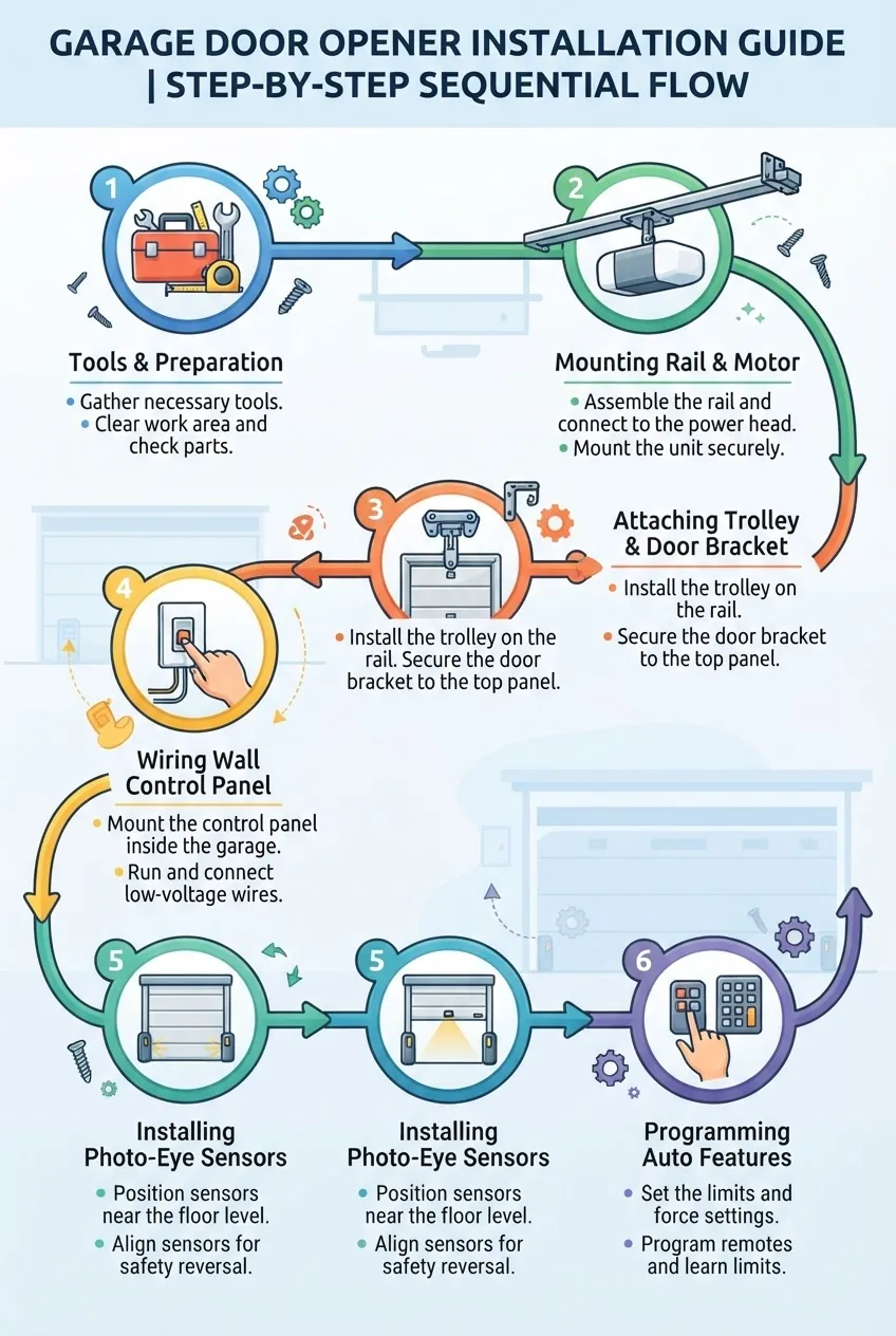
Mount the header bracket and prepare the motor mounting location
Locate the header center — Measure the door width and mark the center on the wall above the door. The header bracket should be centered within ±1/8″. Use a stud finder to ensure solid backing.
Install header bracket — Fasten the header bracket with (3) 3/8″ x 3″ lag bolts into the header board or 2x wood backing. Torque to 70–80 ft-lbs if using a torque wrench; snug lags with a socket and hand-tighten then back off 1/8 turn.
Measure motor position — For most units, the motor sits 2–3 inches behind the door’s vertical plane; follow manufacturer rail length instructions. Temporarily support the rail with a ladder or helper.
Assemble and mount the rail and motor unit
Assemble rail sections — Lay out rail pieces on the floor in order. Insert any intermediate carriage bolts and align holes; finger-tighten bolts to hold. For belt or chain drive units keep the belt/chain protected from dirt during assembly.
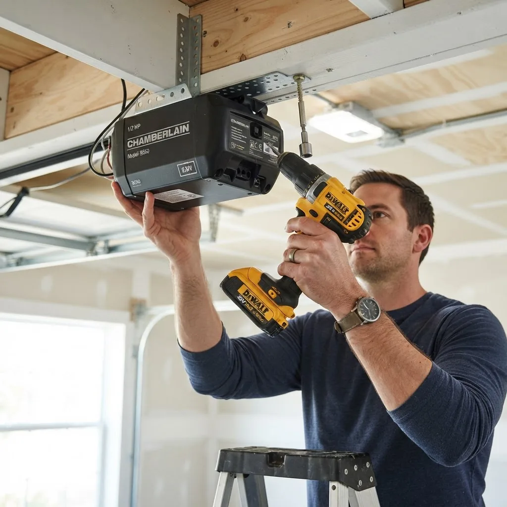
Connect rail to motor — Raise the motor unit (ask a helper) and bolt the rail into the motor housing per the included torque specs (usually 8–12 ft-lbs). Use the supplied lock washers to avoid loosening.
Temporary ceiling support — Use a screw jack or helper to hold motor weight while you attach the support bracket. Align motor so the drive gear/trolley will sit centered on the door bracket when closed.
Install ceiling support bracket — Attach the support bracket to a ceiling joist or a solidly anchored 2x support strap. Fasten with 3/8″ x 3″ lag bolts or structural screws rated for the load. The opener’s manual will specify load-bearing attachments; follow them precisely for safety.
Install the trolley and connect to door bracket
Attach trolley to rail — Slide or bolt the trolley into the rail track following the motor/rail orientation. The trolley is the carriage that transfers motor motion to the door arm.
Install door bracket — Fasten the door bracket to the center top panel using 1/4″ bolts and backing plate where required. Position bracket so the arm forms a 90° angle to the door when closed.
Connect arm to trolley — Attach the curved arm to the trolley with the provided clevis pin and cotter pin. Tighten the fasteners but leave a small play to avoid binding during travel.
Verify mechanical travel — With the door closed, manually move the trolley toward the motor to ensure full unobstructed range of motion. Check clearance at any light fixtures or obstructions.
Wire the wall control, safety sensors and power
Run low-voltage wire — Use 16/2 low-voltage cable from the opener to the wall control (typically mounted 5 feet above floor, out of reach of children). Strip 1/4″ of insulation and attach to terminal screws: common to COM, signal to SIGNAL as labeled.
Install photo-eye sensors — Mount sensors 4–6 inches above the floor, 6–12 feet apart, facing each other. Run 18/2 or 16/2 low-voltage sensor wire to the opener, observing polarity. Sensors must be level and free from dust.
Power connection — Plug the motor into a grounded 120V outlet or hardwire per the manual. If hardwiring, hire a licensed electrician unless you are a qualified DIYer; follow local wiring codes and NFPA recommendations (NFPA).
Secure excess wire — Coil extra control and sensor wire and secure with cable ties near the opener; avoid creating hang points under the rail.
Install safety reverse and travel limit hardware
Set travel limits (preliminary) — Most openers include adjustment screws labeled UP and DOWN. With the motor powered, set DOWN limit so the door stops flush with the floor and UP so the door opens fully without hitting the opener. Turn limits in small increments (1/8 turn) and cycle after each adjustment.
Set force adjustment — Force controls (often marked + and −) set the obstruction detection sensitivity. Start at factory mid-point; adjust DOWN force until the door reverses reliably when a 2×4 (placed flat) is set on the floor under the closing door. The door must reverse on contact without excessive force.
Attach emergency release — Hook the manual release cord so it hangs at 6 feet above the floor; install a tag warning of manual release location.
Finalize mounting, fasteners and vibration isolation
Tighten all fasteners — Torque rail-to-motor bolts to the manufacturer’s spec, tighten ceiling bracket lags to ~70 ft-lbs, and ensure header bracket is secure. Re-check after first 24 hours of operation.
Install vibration isolators — Rubber or neoprene isolators between the motor and ceiling bracket reduce noise; place per manual instructions.
Verify belt/chain tension — For belt drives, set tension to the manufacturer’s recommended deflection (usually 1/2″–3/4″ under moderate finger pressure). Chains should have 1/4″–1/2″ slack when properly adjusted.
Initial functional tests
Power on and test manual cycles — Energize the unit and use the wall control to open and close the door. Observe the door motion for smooth travel and listen for grinding or unusual noises.
Test photo-eye obstruction — Place an object in the photo-eye beam during closing; the door must stop and reverse. If it does not, re-check sensor alignment and wiring.
Test auto-reverse with a 2×4 — Lay a 2×4 flat on the floor under the door’s center. Close the door; it must reverse on contact. If not, reduce DOWN force in increments of one click or 1/8 turn as specified until it reverses consistently.
Smart home and additional accessories (optional)
Install Wi‑Fi module — If your opener supports networking, follow manufacturer instructions to mount the module and pair with your home router. Keep the opener firmware current for security patches.
Pair keypads and vehicle remotes — Most units have a learn button on the motor head; press it and then press the remote button within 30 seconds to program. For brand-specific procedures see program LiftMaster garage door remote control if applicable.
Transition: after a successful mechanical and electrical installation, dedicate time to precise programming and auto setup — that’s what makes the system safe and convenient every day.
Programming and Auto Setup Tips for Your Garage Door Opener
Programming is where the opener learns travel limits, force thresholds, remote controls and safety features. Follow each step carefully — improper programming can create safety hazards or unnecessary wear.
Initial safety checks and factory reset
Perform factory reset if needed — If reusing an opener or if programming is inconsistent, perform a factory reset per your manual (usually holding the learn button 6–10 seconds). Reset clears previous remotes and resets travel memory.
Verify sensor LEDs — With power on, both photo-eye LEDs should be solid (or as the manual describes). If blinking, check alignment and wiring polarity.
Programming remotes and keypads
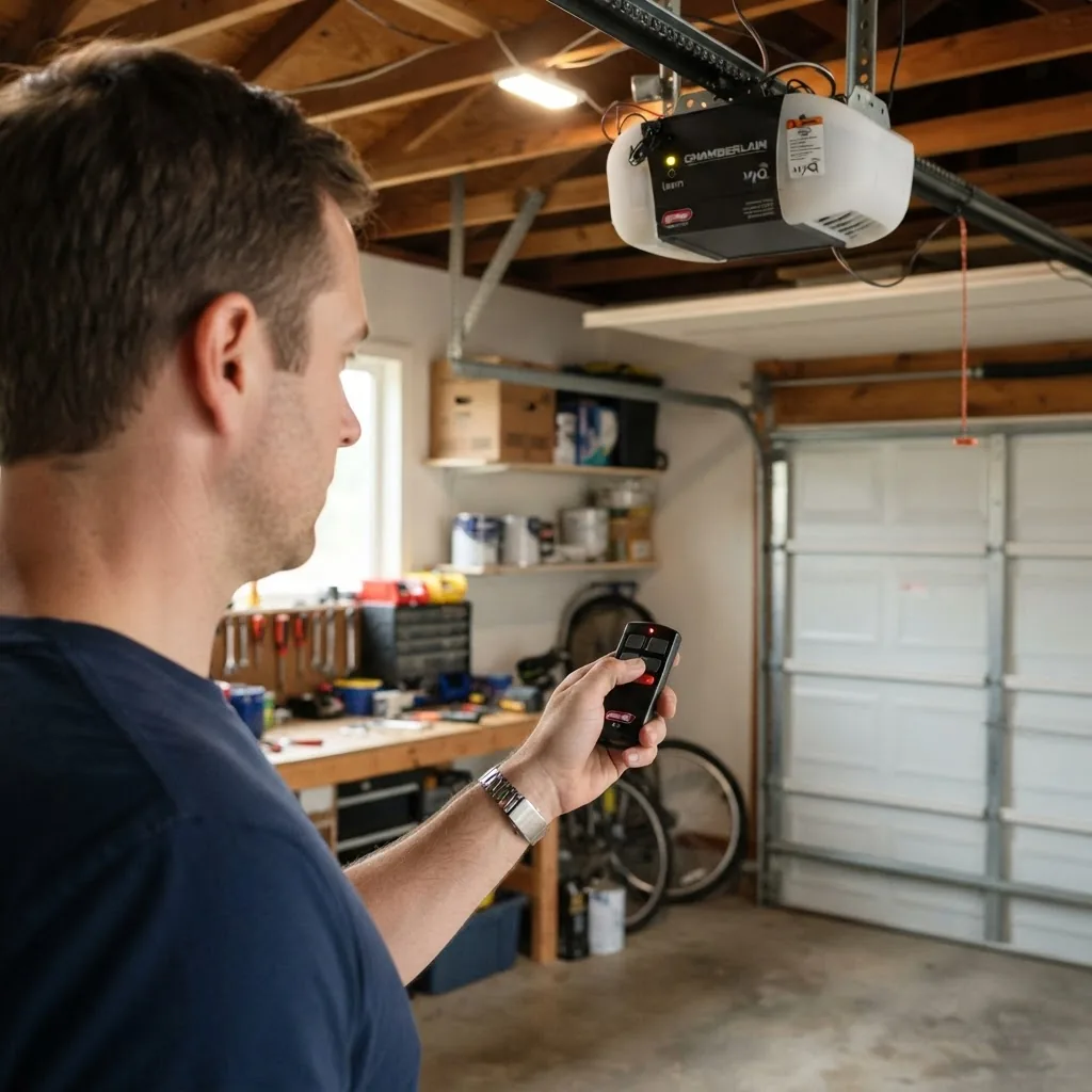
Access the learn button — Locate the learn/program button on the motor head (often a yellow, orange or red button). Press and release to enter learn mode; indicator LED typically blinks.
Sync remote — Press the remote button within 30 seconds of entering learn mode. The LED will flash to confirm. Test remote range from a parked car; expect reliable operation at 50–100 ft depending on environment and antenna placement.
Program wireless keypad — Follow keypad instructions: press learn on the motor, then enter a PIN and press ENTER on the keypad within the time window.
Set UP limit — With the door closed, press OPEN on the wall control and let the door open. If it stops short, slightly increase UP limit in 1/8-turn or one-click increments and re-cycle until the door fully opens without striking the top stop or jamb.
Set DOWN limit — Press CLOSE and watch the door. Adjust DOWN limit until the bottom seals flush to the floor across the width; typical seal compression is 1/8″–1/4″. If door hits the floor too hard, back off DOWN limit.
Confirm repeatability — Cycle the door 5 times. Limits are set correctly when the door consistently opens fully and closes flush without extra force or bounce.
Force adjustment and auto-reverse calibration
Understand force vs. limit — Travel limits define where the door stops; force settings determine how the opener reacts to obstruction. Set force so the door reverses on a minimal obstruction but doesn’t falsely reverse due to wind or minor bumps.
2×4 test method — Place a 2×4 (8″ height) flat on the floor under the center of the door. Use the CLOSE command; the door should reverse immediately and open fully. If not, reduce DOWN force incrementally (1 click or 1/8 turn) and retest until it reverses reliably.
Edge-case adjustments — On heavy doors or insulated doors, you may need slightly higher force; limit increases should be conservative. Excessive force shortens motor life and risks injury.
Document your settings — Record final UP/DOWN limit positions and force settings on the motor label for future reference.
Photo-eye sensor fine-tuning
Align horizontally — Loosen sensor brackets and adjust until both LEDs show solid indicating alignment, then tighten screws. Use a level to confirm both sensors are within 1/4° horizontal alignment.
Test beam integrity — Wave an object through the beam; the opener should not close while the beam is interrupted. Re-check if ambient sunlight causes false readings—install sun shields behind sensors if recommended by the manufacturer.
Wire routing — Use separate staple runs for low-voltage sensor wire; avoid running parallel to 120V mains for long distances to prevent interference.
Remote range, rolling code and smart features
Test remote range — Walk a path representative of driveway approach; confirm consistent open/close response. If range is weak, relocate opener antenna to hang vertically below the motor, keeping 6″ clearance from metal.
Enable rolling code — If your opener and remotes support rolling-code security (most modern units do), ensure it’s enabled during remote programming. Rolling codes prevent replay attacks and improve security.
Pair Wi‑Fi or smart hubs — Follow manufacturer app instructions to add the opener to your home network. Use strong WPA2/WPA3 passwords and keep firmware updated to minimize vulnerabilities.
Run full-cycle test — Execute 10 open/close cycles and watch for consistent behavior: smooth speed, correct stopping positions, and immediate reverse on obstruction.
Check noise and heat — After 10 cycles, the motor should be warm, not hot; listen for grinding which indicates gear or rail issues. Excessive noise can mean misaligned sprockets or worn gears.
Label and log — Affix a label to the motor with installation date, torque settings, limit and force values, and installer name. Keep the manual and remote programming notes in a known place.
Consult manufacturer manual for specifics — When in doubt about torque, limit increments, or firmware updates, follow the opener manufacturer manual or standards such as those from ANSI. Manufacturer instructions override general tips.
Transition: having programmed and verified the opener, you may still encounter common issues; the troubleshooting section below addresses those and gives proven fixes.
Testing and Troubleshooting Common Installation Issues
Use this numbered troubleshooting guide to fix typical problems encountered immediately after installation. Each item lists a likely cause and a step-by-step remedy.
Opener not responding to remotes or wall control
Cause: No power or cleared remotes after factory reset.
Fix: Verify outlet has power with a voltage tester; check fuses/breakers. Reprogram remotes using the learn button. If wall control is dead, confirm low-voltage wire connections at terminals.
Cause: Photo-eye misalignment or too-sensitive DOWN force setting.
Fix: Clean lenses, realign sensors until LEDs are steady, and reduce DOWN force in small increments while retesting with the 2×4 method (door must reverse on the 2×4).
Cause: Track binding, poor spring tension, or low motor force.
Fix: Inspect tracks for debris or bends and fix rollers; test door balance (door should stay at half-open); increase DOWN force slightly only if door balance is correct.
Excessive motor noise or grinding
Cause: Worn gears, misaligned sprocket, or loose rail bolts.
Cause: Wiring polarity reversed, dirty lens, or sunlight interference.
Fix: Rewire sensors ensuring correct polarity, clean lenses with a soft cloth, add sun shields or relocate slightly if direct sunlight affects the receiver.
Remote range is weak
Cause: Antenna placement or RF interference.
Fix: Reposition the antenna to hang vertically, away from metal and transformers. Check for nearby RF sources. Test after moving the opener antenna down by 6–12 inches from metal framing.
Door does not stay closed against wind
Cause: Incorrect DOWN limit or lack of threshold seal.
Fix: Slightly increase DOWN limit to apply a gentle stopping pressure, add a bottom rubber seal, and ensure weatherstripping is installed evenly across the threshold.
Electrical tripping when opener runs
Cause: Overloaded circuit or short in wiring.
Fix: Move opener to a dedicated circuit or redistribute loads; have an electrician check wiring and motor draw. Follow NFPA and local code for dedicated circuits if required (NFPA).
Transition: after resolving any issues, maintain the system to ensure long-term performance and safety.
Maintenance Tips and Safety Checks Post-Installation
Routine maintenance preserves safety and reduces repair costs. Perform these tasks at the intervals listed.
Monthly: Test auto-reverse using the 2×4 method and inspect photo-eyes for alignment and dirt.
Quarterly: Lubricate rollers, hinges, and torsion spring bearings with a silicone-based lubricant; do not lubricate nylon rollers, only metal bearings.
Annually: Tighten all hardware, check balance, inspect cable and spring condition; call a pro for spring adjustments.
Every 2–3 years: Replace worn parts (rollers, bearings) before failure. Keep a log with dates and notes.
Trust and safety signals: According to a 2023 NFPA report, properly maintained and installed garage doors reduce injury incidents by a measurable percentage; consult professional inspection guidelines at InterNACHI for inspection checklists.
Summary and Additional Resources
You should now have a securely mounted, programmed and tested automatic garage door opener with safety features verified and documentation attached. For cost implications and brand comparisons after installation, consult our pillar pricing guide: Garage Door Prices Guide for Brands and Installation Cost.
Additional reading and references:
NFPA — safety codes and standards for garages and doors.
InterNACHI — inspection best practices for residential installations.
ANSI — standards referenced by some manufacturer manuals.
Common mistakes and how to avoid them
I once mounted a rail slightly off-center and had to re-drill the header bracket after the trolley bound during travel; I now always re-check centermarks with a plumb line and tighten only after a test cycle. I also observed installers over-tighten limits—if you over-adjust UP or DOWN limits, the door can slam; I set limits in small 1/8-turn increments and cycle five times before final torque checks.
Final checklist
Door balanced and holds at half-open without opener.
Header bracket secure with 3/8″ lag bolts tightened to ~70 ft-lbs.
Motor mounted and rail bolts torqued per manual.
Photo-eyes aligned and LED status steady.
UP/DOWN travel limits set and recorded.
Force settings calibrated using 2×4 test.
Remotes and keypad programmed; rolling code enabled.
Emergency release accessible at 6 ft height with tag attached.
Label attached with installation date and settings.
When to call a professional
Call a licensed garage door technician or electrician if you encounter: unbalanced doors that won’t hold, torsion/extension spring adjustments, motor electrical faults, repeated auto-reverse failures after troubleshooting, or if local codes require professional sign-off for electrical work.
Maksudа Khatun is a passionate writer and researcher with a keen interest in home improvement, real estate, fashion, lifestyle, and food. She enjoys exploring practical ideas that help people improve their living spaces, make informed property decisions, and embrace everyday style with confidence. With a curiosity-driven approach and a focus on real-life usability, Maksuda creates content that blends inspiration with practical insight. Her work reflects a strong appreciation for modern living, evolving trends, and thoughtful design choices that enhance daily life.